
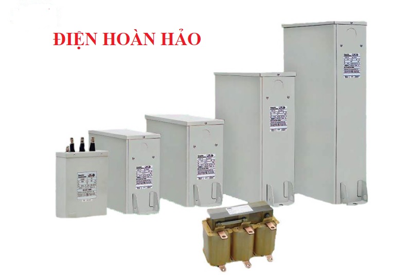
Tụ bù ABB
Technical specifications
|
Voltage range |
From 220 to 1000 V. |
|
Frequency |
50 and 60 Hz. |
|
Connection |
Three-phase as standard construction (single-phase on request). |
|
Discharge resistors |
Permanently connected built-in discharge resistors are sized to ensure safe discharge of the capacitor to less than 50V in 1 minute after a switch off. Minimum time between disconnection and re-energization: 40 seconds. |
|
Terminals |
CLMD13: three M6 terminals. CLMD33S: three cable outputs (6, 10, 16 mm²), 50 cm long.CLMD43-53-63-83: with threaded rods M6, 8, 10 or 12 according to the power of the capacitor. |
|
Earth |
CLMD13-33S: earth connection on the enclosure fixation. CLMD43-53-63-83: a M8 terminal is included under the cover. |
|
Cable input |
By a knock out: CLMD13: 22.5 mm. CLMD33S: 500 mm CLMD43-53: 37 mm. CLMD63-83: 47 mm. |
|
Case material |
Zinc electroplated mild steel. |
|
Color |
Beige RAL 7032. |
|
Fixing |
CLMD13: with two slots, diameter 6.5 mm (suitable fixing for assembly in module). CLMD33S: with eight fixation holes, diameter 5.4 mm. CLMD43-53-63-83: with two slots 26 X 12 mm. |
|
Execution |
Indoor (outdoor on request). |
|
Protection |
CLMD13-43-53-63-83: IP 42 (IP 54 on request). CLMD33S: IP40. |
|
Maximum ambient temperature |
Class „D“ (+55°C) according to IEC 60831. |
|
Minimum ambient temperature |
Indoor type: -25°C. Outdoor type: -40°C. |
|
Minimum distance between units |
CLMD13-33S: 20 mm (25 mm for units > 30 kvar). CLMD43-53-63-83: 50 mm. |
|
Minimum distance between units |
CLMD13-33 : 20 mm (25 mm for units > 30 kvar). |
|
and wall |
CLMD43-53-63-83: 50 mm. |
|
Losses (discharge resistors included) |
< 0.5 Watt/kvar for 380 V rated voltage and above. |
|
Tolerance on capacitance |
0 % + 10 %. |
|
Voltage test |
Between terminals: 2.15 Un for 10 seconds. Between terminals and earth: 3 kV for 10 seconds for UN < 500 V and 4 kV for 10 seconds for UN > 500 V. |
|
Lightning impulse voltage test |
CLMD13-43-53-63-83: 15kV. CLMD33S: 8kV. |
|
The acceptable overloads are those |
Overvoltage tolerance: 10% max. at intervals. |
|
specified in IEC 831-1&2 |
Overcurrent tolerance: 30% permanently. |
|
|
Maximum overload: stable operation at 135% of the nominal rating (generated by overvoltages and harmonics). |
Selection table
|
Voltage (V) |
Power (kvar) |
CLMD |
Ordering code |
Weight (kg.) |
|
525 |
5 |
13 |
2GSB010419A0022 |
2.0 |
|
525 |
10 |
13 |
2GSB010176A0022 |
2.5 |
|
525 |
15 |
13 |
2GSB010180A0022 |
2.5 |
|
525 |
20 |
43 |
2GSB010183A0022 |
4.5 |
|
525 |
25 |
43 |
2GSB010184A0022 |
5.0 |
|
525 |
30 |
43 |
2GSB010187A0022 |
6.0 |
|
525 |
35 |
13 |
2GSB010188A0022 |
10.0 |
|
525 |
40 |
13 |
2GSB010450A0022 |
11.0 |
|
525 |
50 |
53 |
2GSB010453A0022 |
13.0 |
|
525 |
60 |
63 |
2GSB010454A0022 |
14.0 |
|
525 |
70 |
63 |
2GSB010455A0022 |
15.0 |
|
525 |
75 |
63 |
2GSB010423A0022 |
15.5 |
|
525 |
80 |
63 |
2GSB010174A0022 |
16.0 |
|
525 |
85 |
63 |
2GSB010424A0022 |
17.0 |
|
525 |
90 |
83 |
2GSB010425A0022 |
19.0 |
|
525 |
100 |
83 |
2GSB010177A0022 |
21.0 |
|
525 |
120 |
83 |
2GSB010179A0022 |
22.0 |